

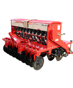
TRSAYA-507
Tar River 78″ No-Till Drill | CAT 1/2 | 10 Seed & Fert Cups | Spaced 7″ | 35 HP Min | 3/4″-2″ Depth
$7,800.00
Weight: 1400lbs
Tar River No-Till Drills
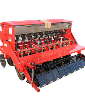
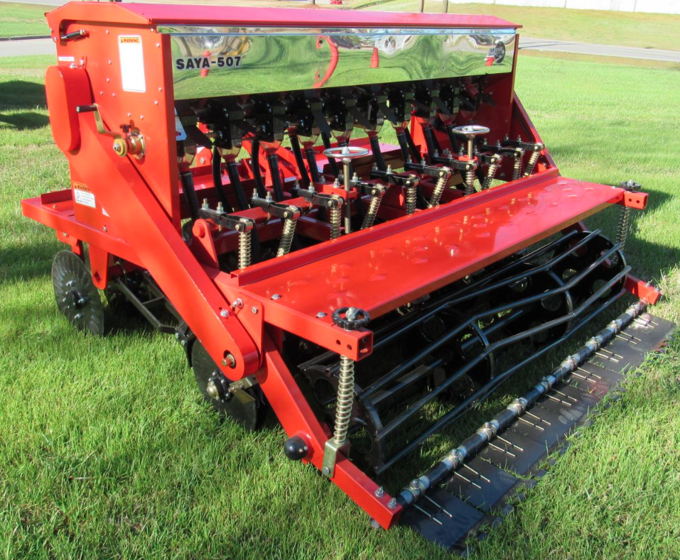
The SAYA Drill is a cost effective light duty no-till drill with front coulter package. They have swept back spring loaded double disc openers to make seeding easy & economical. They also have 2 Separate boxes with large seed & the other with legume cups to allow for precise seeding in a no-till operation. Stainless steel hoppers prevent rust and keep your drill in fine working shape for years to come.
- 7.5″ Spacing
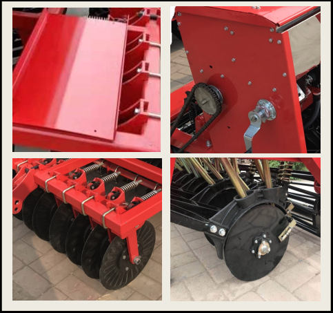
- Spring Loaded Coulter Discs
- Spring Loaded Double Disc Opener With Cast Iron Hubs
- Cast Iron Sweptback Disc Carriers
- Disc Scrapers
- Divided Stainless Steel Hopper
- Standard Seed / Fertilizer Seed Cups On Front
- Legume Seed Cups On Rear
- Full Width Cage Roller
- Compaction Scrapers

| Model | Working Width | Working Depth | Min HP Req | # Seed Cups | # Fert Cups | Cat. Hitch | Weight |
|---|---|---|---|---|---|---|---|
| SAYA-505 | 55″ | 3/4″ – 2″ | 30 | 7 | 7 | 1 & 2 | 1036 lbs. |
| SAYA-507 | 78″ | 3/4″ – 2″ | 35 | 10 | 10 | 1 & 2 | 1400 lbs. |


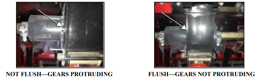
Before Beginning Work
- Be sure all the seed cups completely close and open the same, so all cups are putting out the exact amount of seed. If they are not in sync, one cup will put out more than others.
- Ensure when completely closed, the seeding gears are not protruding from the outside the cup.
- Adjust the clamps to ensure all cups close and open completely and uniformly.
To Adjust Seed Output
The Seed cups on the SAYA may come with either of two different style of seed cups or a combination of both. Typically the front Seed box section is equipped with a “Large Seed Cup” and the rear section typically has the Legume Seed Box.

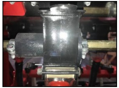
SAYA Seed Cups
The Large Seed front section is usually driven with an 11-26 Gear ratio, while the back Legume Seed section is being reduced to put out less with a 12-40 Gear Ratio.
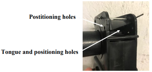
Seeding/Fertilizing Rate Adjustment Handle
To adjust the fertilizer rate, you will need to adjust hand wheels (on each side of hopper).The seed/fertilize rate depends on the seed/fertilizer you want to plant, please refer to your seed/ fertilizer supplier’s chart to get the proper seed/fertilize rate. Before adjusting the seed rate, return the rate on the Scale to zero by rotating the hand wheel, then check and make sure all seeding/fertilizing wheels are fully closed on all seeding/ fertilizing boxes. (SEE BEFORE BEGINNING section) If not, you need to loosen the clips on both sides of the seeding/fertilizing wheel and push the wheel into the box. Tighten the clips. When the seeding/fertilizing box is closed and the meter indicates “0”. Adjust fertilizing rate by rotating the hand wheel. The meter has 8 numbers from 0-8, from zero to Maximum. Weight, size, relative humidity, and moisture content can affect seeding rates. Users can adjust the position of the seed/fertilizer “TONGUE” and lock in different positions by moving the cotter pin to meet the different seeding/fertilizing size. The smaller the seed, the higher up the TONGUE should be positioned. For larger seed, the “TONGUE” should be opened more.
Important: Tighten locking nut on handle assembly before operating.
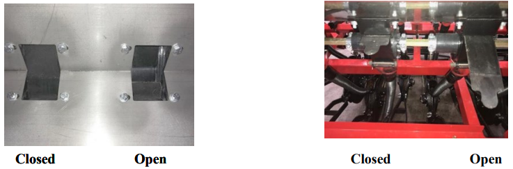
Seed Cup Shutoff
Depending on the crop being planted, it may be necessary to not disburse from all of the seed cups. This is easily done by simply sliding the “Seed shut off flap” in and out.
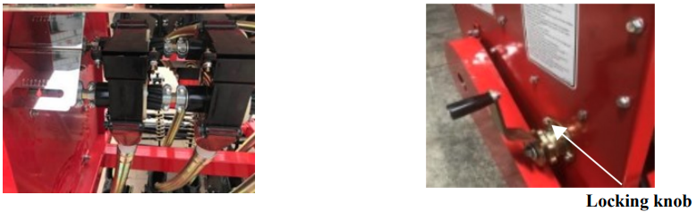
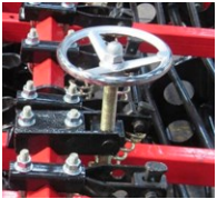
Seed Depth – Rear Roller
The depth in which the application is done is controlled by adjusting the basket located near of the machine. Adjusting the “Sowing depth control device “ as follows: Turning knob counter-clockwise will make the basket drop which in turn will raise the disc openers and lessen the depth of the application. Turning the knob clockwise would raise the basket which would lower the disc openers and make the application deeper.
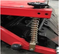
Seed Depth – Torsion Bar
Turning the Torsion Bar wheel will increase spring tension on the individual discs to apply additional pressure.
Seed Depth – Disc Support Bar
The top link on the tractor hitch should be properly adjusted to carry the machine level in an operating position. During operation, the tractor lift must be fully lowered to allow the machine to follow the contour of the ground. The machine is totally ground driven so proceed with a speed that is most comfortable and safe for existing conditions. Be sure to stop forward motion before lifting the machine off the ground. This practice will stop rollers from “free spinning’ and therefore eliminate the unwanted application when turning around. Never operate the machine in reverse. Additional pressure can be added by moving the curved clip into another hole on the Disc Support Bar.
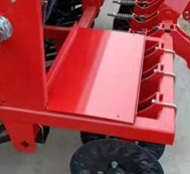
Additional Weight Platform
Important: The machine comes equipped with additional weight platforms to help penetrate harder soils. Do not overload!
Disc Alignment
The Disc Support Bracket must be in the correct orientation prior to operating the implement. The corners of the Disc Support Bar must be in the 12 O’clock, 3 O’clock, 6 O’clock & 9 O’clock positions. The Disc Support Bracket will be parallel to the ground, Fig. “A”.
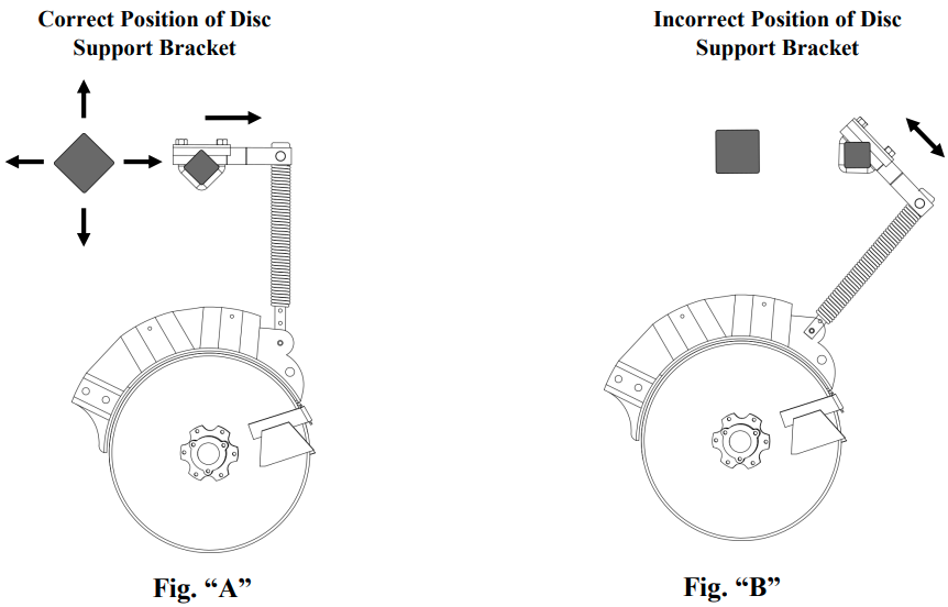
If the Disc Support Bracket is not parallel to the ground, as shown in Fig “B”, disconnect the Disc Support Brackets and Torsion Bar Clamp, Fig “C”.

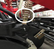
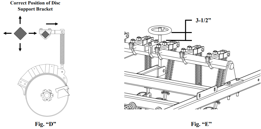
Disc Alignment (Cont.)
Position the Disc Support Bar as shown in Fig. “D”. Adjust the Torsion Adjustment Wheel so that the threads are about 3-1/2” from the threaded bracket to the adjustment wheel, Fig. “E”. Be sure to tighten all hardware before operating the implement.
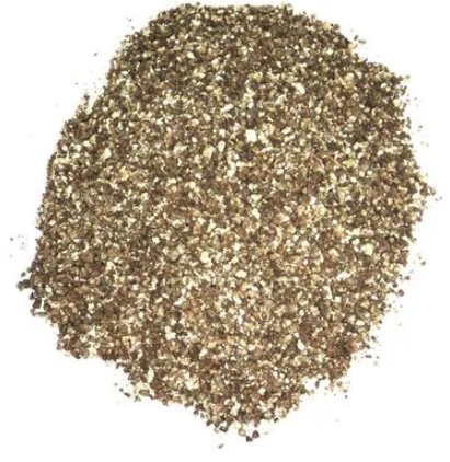
What Agents Can I Use As A Filler To Reduce Application Rate?
Below is a list of agents that may be used as filler to reduce the application rate on Seeders. This list is not a complete list and intended only to be an aid in reducing the amount of seed dispensed. You must evaluate what would be the best thing to add to the particular seed you are dispensing.
1. Vericulite Fertilizer
2. Malorganite Fertilizer
3. Rice Hulls
4. Kitty Litter
5. Coarse Saw Dust
6. Pelletized Lime
7. Cracked Corn
8. Oats
9. Wheat


| Weight | 1400 lbs |
|---|