
WFA538RD
Westfield 10″ Electric Hopper Winch | For MK/MKX/MKX2-100’s WITH Electric Powerswings
$3,410.00
WFA538RD Applicable To 10” Auger Series When Integrated With An Existing Electric Power Swing
Steps for Add-On Kits Installation-
Step 1: Install the Electric Winch
- Follow the same winch installation process as outlined for standalone kits (Step 1).
Step 2: Install the Boot Switch
- Follow the same boot switch installation process as outlined for standalone kits (Step 2).
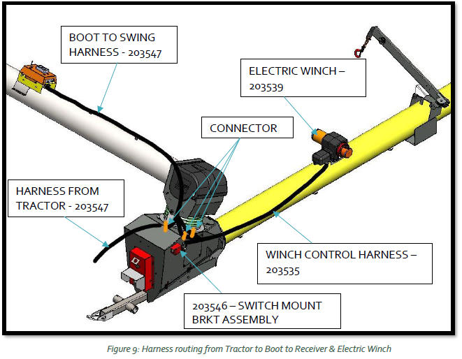
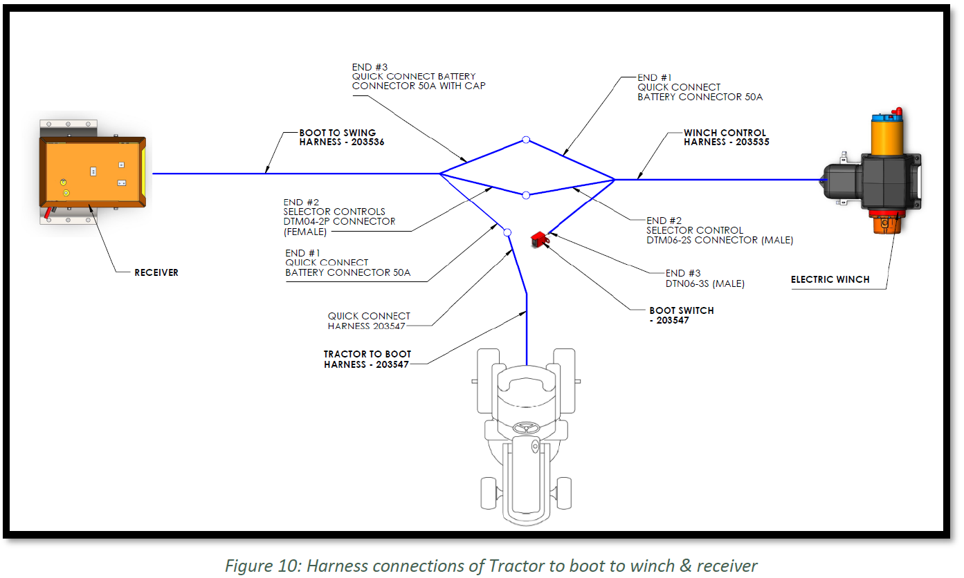
Step 3: Route the winch control harness (203535) and boot to swing harness (203536) to the boot as shown in Figure 9 and connect both to tractor harness and boot switch as shown in Figure 10. Fasten Harnesses to cable clamps after connecting.
Step 4: Battery connections (Tractor Harness)
- Follow the same tractor battery connections process as outlined for standalone kits (Step 4).
Step 5: Wiring Connections for Add-On Kits
A. Attach tractor wire harness (203547) quick connect to the receiver cable (203536) quick connect battery connector 50A (END #1) as shown in Figure 10.
B. Attach winch control harness (203535) quick connect battery connector 50A (END #1) to the quick connect battery connector 50A with cap (END #3) of boot to swing harness (203536) as shown in Figure 10.
C. Connect selector controls connectors male/female (END #2) of both harnesses, 203535 and 203536 as shown in Figure 10.
D. Connect quick connect of E-winch switch (203546) on the boot to END#3 of winch control harness (203535) as shown in Figure 10.
STEP 6: Assembly instructions for Electric Winch Receiver:
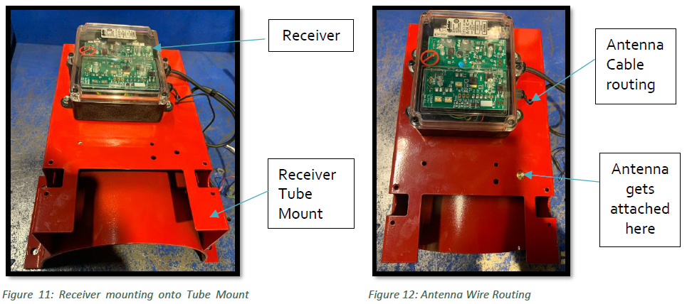
A. Take part #203540RD/203542RD (10”/13” RECEIVER TUBE MOUNT) and Part #20135 (RECEIVER, REMOTE CONTROL – LODAR), use #14 X 5/8” Sheet Metal Screw (19274) to mount Receiver (20135) onto bracket (203540RD/203542RD) using impact gun with 3/8” socket as shown in Figure 11.
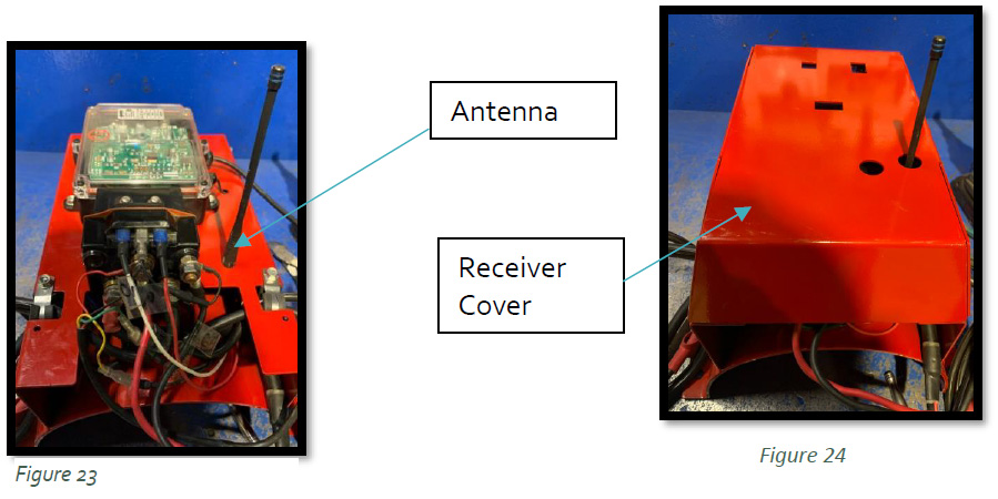
B. Use Pliers to cut the clip holding wires together on Receiver. Unscrew nut and washer on end of antenna cable to be able to fit it through hole. Route antenna wire inside Receiver tube mount as shown in Figure 12. Attach nut and washer back onto screw to secure through hole using 5/16” wrench.
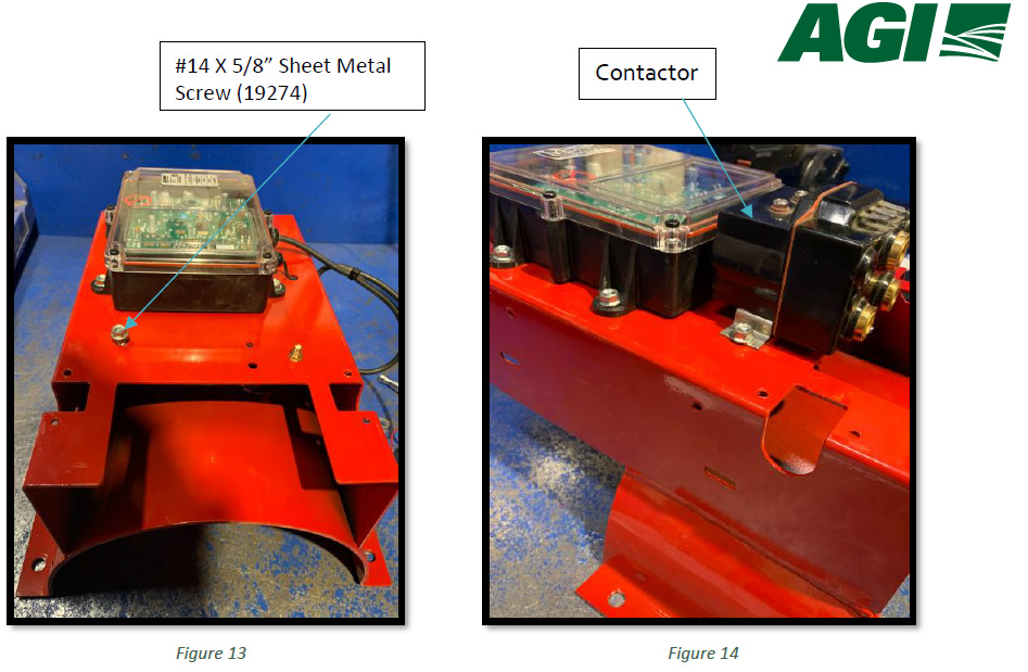
C. Torque #14 X 5/8” Sheet Metal Screw (19274) halfway on one side, leaving room for Part #20136 (CONTACTOR, 80 AMP) to fit underneath as shown in Figure 13. Then, slide contractor under screw, then torque screw all the way down to secure it as shown in Figure 14.
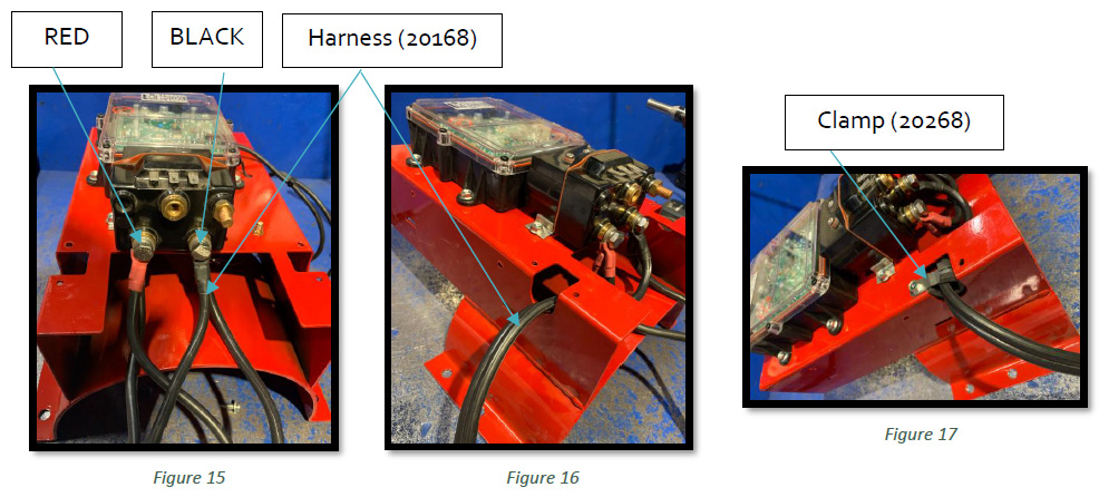
D. Take two of harnesses i.e. Part #20168 (WIRE HARNESS CONTACTOR TO MOTOR), then attach two of same colour terminal connections together with bolt and washer that comes with Contactor, then place on Contactor in the spot as shown in Figure 15. Use ratchet with ½” socket to secure. Route harness to left and right through openings of receiver mount tube as shown in Figure 16. Attach clamps part #20268 (Clamp, 5/8 X 12 INSULATED) to wires, then bolt down wires to top clamp on both sides using #14 X 5/8” Sheet Metal Screw (19274) as shown in Figure 17.
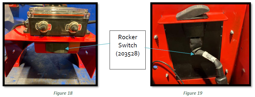
E. Mount Part# 203528 (ELEC, DPDT, ROCKER SWITCH) using snap-in bracket onto Receiver Tube Mount as shown Figure 18 & Figure 19.
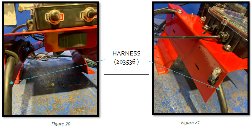
F. Route PART #203536 (HARNESS, BOOT TO SWING) to inside receiver tube mount as shown in Figure 20, fasten on back of receiver mount with cable clamp (20268) as shown in Figure 21.
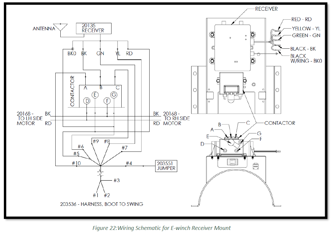
G. Attach wires of Receiver & Harness (203536) to contactor in correct order as shown in Figure 22:
i. Attach small white wire (END #10) of Harness (203536) to terminal ‘A’ of Contactor.
ii. Attach small black wire (BK) of Receiver to terminal ‘B’ of Contactor.
iii. Attach small red wire (END #9) of Harness (203536) to terminal ‘C’ of Contactor.
iv. Attach small grey wire (END #8) of Harness (203536) to green wire (GN) of Receiver.
v. Attach small black wire (END #7) of Harness (203536) to yellow wire (YL) of Receiver.
vi. Attach small black wire with ring (BK0) of Receiver and black hose (END #6) from harness (203536) together onto input terminal ‘G’ of contactor, attach with a washer and nut at the end by using ratchet with ½” socket to secure it.
vii. Attach small red wire (RD) of Receiver and red hose (END #5) from Harness (203536) together onto input terminal ‘E’ of contactor, attach with a washer and bolt at the end by using ratchet with ½” socket to secure it.
viii. Connect Rocker switch (203528) to (END #4) of boot to swing harness (203536).
H. Mount Antenna as shown in Figure 23 and attach receiver cover (57453) and torque #14 X 5/8” Sheet Metal Screw (19274) screws to secure cover down as shown in Figure 24.
I. On the high end of the Power Swing remote receiver box, flip the power switch to the ON position as shown in Figure 25.
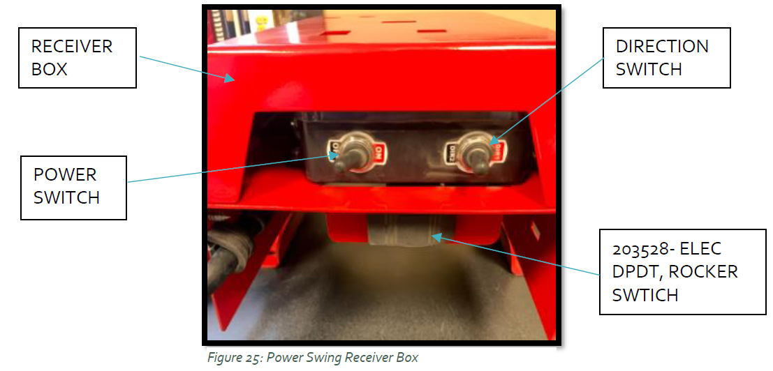
STEP 7: Receiver Box Operation:
A. Using the direction switch, move the switch in the desired direction of travel (either Dir1 or Dir2) as shown in Figure 25.
B. Once finished moving the hopper, release the switch to stop operation.
STEP 8: Remote Transmitter Operation:
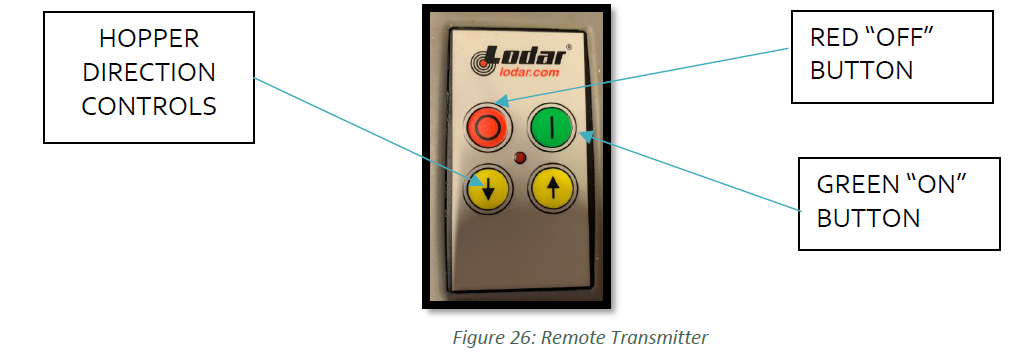
A. Push the green button to turn the remote ON (Figure 26)
B. Push the yellow directional buttons (marked with arrows) located below the ON/OFF buttons in the direction you want the hopper to move (Figure 26).
- If this does not work- Push the red button to turn the remote OFF.
C. Then push the green button to turn the remote back ON.
D. Operate the remote as outlined above, using the two yellow directional buttons (marked with arrows) located at the bottom of the remote to move the hopper as desired.
E. To lift/lower the winch with remote, Flip the switch actuator located on the high end of the Power Swing remote receiver box.